After Kiel brought us the environment for the third part of the animation, I set up the lightings for the scene and Mike animated the camera and rendered the whole scene.
The final animation is less than two minutes long so this is exactly what we wanted to achieve.
Generally I’m quite happy with the final animation. Of course there are many things I would like to change or add, like some effects ( fire, smoke for instance) instead of textures. Besides, I would work a little bit longer on piston animation. To rotate the piston I have used ‘linkedXform’ modiffier. At the beginning it worked well but later we started changing positions of the engine elements (including the piston) so when it goes up it shrinks and when it goes down it stretches. Another thing I think it is important to mention about is the planning. At he beginning we wanted show the piston work from a profile not from the front view. It is important because I could design the lower part of the engine with more details inside.
The first 4-5 weeks were very good and enjoyable because we were the first group that had finished the modelling and started the animation. Then we had the some really basic problems with animation and we also changed the ideas for the animation. As result, we got stuck for a while. (One more thing. We had some problems with 3ds max. In many cases it did not operated the way we had expected. Those problems were solved out personally, on our private computers.)
Just to come back to animation I think it would be nice to put some arrows to indicate which part of the presentation is now discussed.
What I like in the animation? I think the overall animation is quite good. The slow- down and speed-up sections made by Mike work very nice as well as the wire frame effect (the opening shot) looks good. I am really happy that the animation is no longer than 2 minutes, that was something we all kept an eye on. Also we did not want to overload people with the information.Here is the final animation of our group project
Tuesday, 8 December 2009
Final animation
Thursday, 3 December 2009
Animation and Rendering
The last part for me to do, was animation and rendering. I was thinking about animation since the beginning of the project. I knew from the beginning what the group was looking for, we even made a simple storyboard so it was easier to me to choose proper animation tools and techniques to deliver final animation (shots).
We wanted our animation to look like one long animation, without any cut scenes and so on. However, we divided our animation into 3 parts: part one was the introduction, part two was the actual demonstration of the engine, and part three was the ending of the animation (presentation). Also I suggested rendering everything in PAL (24fm/s) rather than in NTSC (30fm/s). (PAL is European standard)
For the first part we wanted to have as we called ‘wire frame effect’. I made a simple try animation of that effect much before: in the first assignment when I animated my head. I did it to show to my group if they liked the idea and I am happy that they agreed with me. This could bring some fresh into animation and also it was a good start. ‘Wire frame’ (that’s how we called this part) scene was actually easy to do. I copied the engine and for the clone one I added the ‘wire’ material. Then I added ‘slice’ modificator to both models. From the options I chose ‘Remove Bottom’ and I moved the slice plane up (just above the engine). I clicked ‘Auto Key’ and simply moved the plane again to the bottom. So the ‘wire engine’ could appear. I used the same method for the second engine although it started a little bit later.
Just to give some more motion to the animation I animated the camera. When the engine begins to appear the camera is moving around, in the same time.
The most difficult, of course, was the second part of the animation.
To ‘cut’ the engine into the half I again used the slice tool. Now the most boring part of animation :) that was the part the group was most afraid of. We wanted to show cycles occurring inside the engine...The first thought was to animate the piston. The only problem was that the piston shaft did not match the cam. We actually got stuck for some time :) Mike found out the problem was with the key frames so they were out of place. After a few adjustments the problem was solved. It’s actually quite funny because this was a very basic issue and I don’t know how I could miss that the key frames were out of place :)
To animate the cycles inside the engine (e.g. air, smoke, fire) I decided to use ‘planes’ with textures. Again I used ‘slice’ for animation. This really saved our time. Thanks for this we avoided any problems with animation, we didn’t have to use any additional software (we thought initially this part should be done in flash). We could concentrate only on the timing. The timing was the only problem we had (e.g. when the fire should happen, for how long, what next, after this and so on). So the timing was the only challenge here. I wanted to create just one cycle so Mike could edit this later and create loop. Mike thought it was important to show reaction on spark plug. So I added glow option to spark plug and I animated the intensity value. In ‘Curve Editor’ I placed key frames in proper place.
The third will be finished on Friday (I hope so). For this part Kiel will create the environment when Eleine creates mower.
As for the rendering. Everything is or will be rendered in PAL format. As for the rendering type I kept the ‘Scanline Render’. I was thinking about Mental Ray but Scanline satisfied my group members so I decided to stick with the Scanline
Textures and Background
Mike was responsible for textures because he is good at Photoshop. He delivered textures for: fire, air and smoke. I also gave him my metal textures so he could give some adjustments to them. When he delivered everything, it was my turn to put these textures into the 3D models. I used ‘UVW map’ to texture the models. To have a nice shining look I increased values of the ‘Specular’ Level’ and ‘Glossiness’ in the Material Editor. I also applied ray trace reflection to the flywheel texture so the model would reflect environment. I believe, later on, Mike changed the flywheel material into more “goldish” :) and I think It looks better :)


The same day when we finished textures I started making the scene for the animation. From the beginning (first meeting) I explained to the team my idea of the background colour and the overall look of the scene, and from the first meeting we didn’t change the idea. Probably, that was the only thing we did not change :)
For the background I wanted to have something simple, which will help focus potential viewers on the engine not on the environment (scene). I also wanted this to look aesthetic and light. I opened the ‘Material Editor’ window. From the Material Editor I selected the clear ‘sphere’, then from ‘Material’ I clicked ‘Get Material’

From the list, I chose ‘Gradient’. So, when I created 2D map for the background, I opened the ‘Environment and Effects’ window. I dragged the gradient material into the ‘none’ button in Environment window and chose the ‘Instance’ option. Thanks to this, when I changed gradient colours in material editor, all the changes were added in environment automatically
When the background was completed I put some omni lights to the scene. So the scene and engine are lighter.

I thought it would be nice to have a shadow. The problem was the scene did not have a floor so the shadow would be visible. However I didn’t want another ‘visible’ model in the scene except the engine. In other words I wanted to have invisible floor. This was easily done. I created a normal plane and from material editor I added ‘Matte/Shadow’ material. So the scene has the floor which is not visible but it shows shadow.


Saturday, 28 November 2009
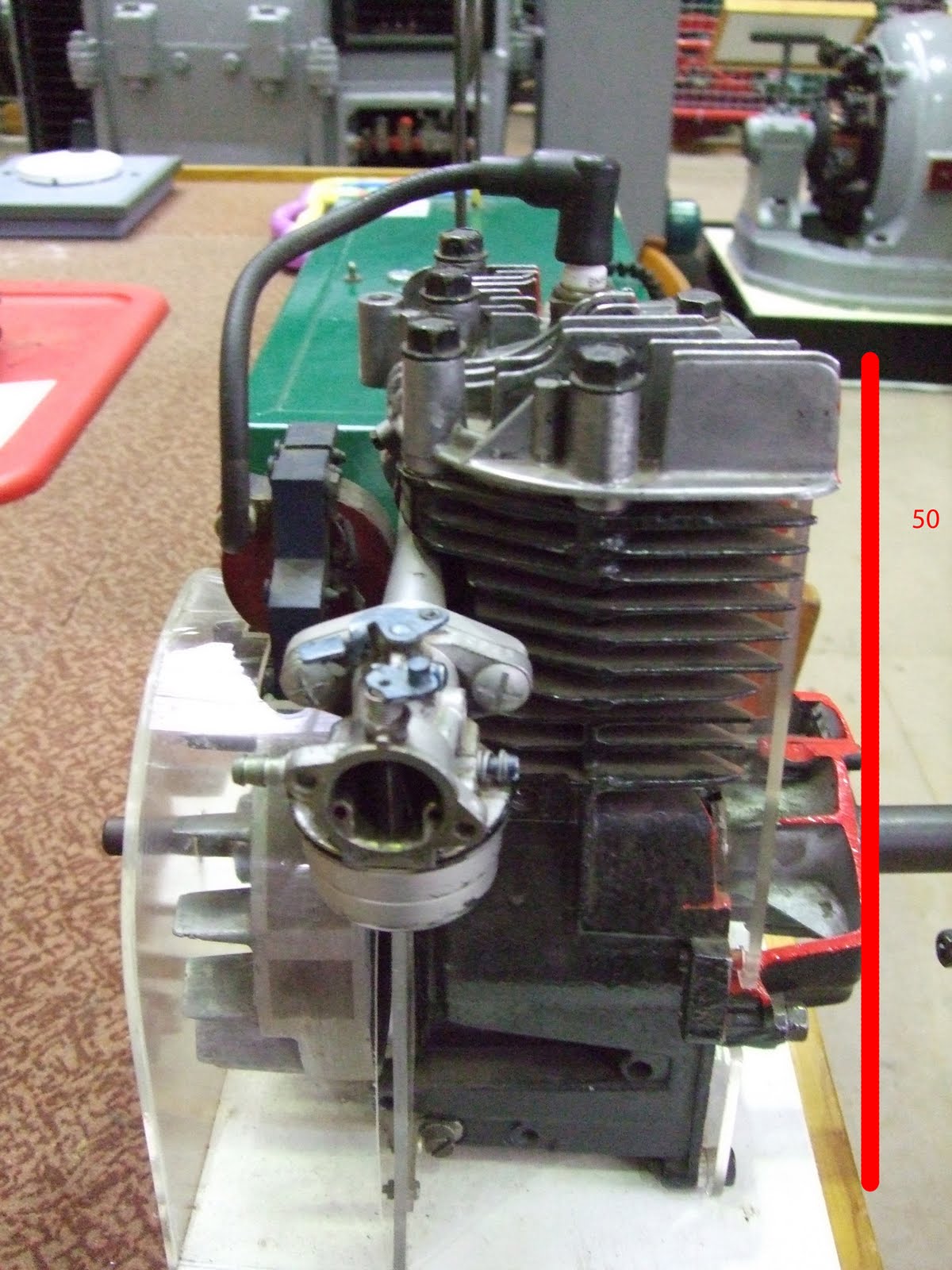
Museum of Power - 2 stroke engine
Our job was to choose one of the engines from the Museum of Power and design a nice animation/presentation for it.
We decided to animate 2 stroke engine.
In the very first group meeting we discussed modelling and ideas for the final animation. This was really helpful to each of us because we knew what must be done, what would be animated and so on. So we could organise our work. We also decided to make group notes every week. As it turned out I noticed that both Mike and me have the latest 3ds Max version whereas Shou has 3ds Max 9 and Kiel - 3ds max 8. So we decided we would do all the animation in university Max version (3ds Max 9). Mike and me will save all the models without any textures of 3ds format, so that we could export these files into older versions of 3ds Max.
Modelling
At the beginning of the project I proposed to my team members that it would be better if each of us was responsible for particular part of the engine. Just before we started modelling we had set up the scale for the pictures. The reason was to keep the original aspect ratio. We could always scale our parts the way they fitted each other.
So when we set up the scale and assigned job to everyone, I started my modelling. I was responsible for the lower part of the engine and the flywheel. At the beginning it seemed to be easy to do but it wasn’t. The pictures that Mike had prepared, were not good enough, unfortunately. The problem was I couldn’t see some of the details and sometimes it was a bit confusing how the particular part should look. I couldn’t find any similar model in the internet so I just tried to make this look as close to the picture as possible.
Anyway I started from flywheel

For example to create those big circles? I have used ChamferCylinder (to have smooth edges). I turned the cylinder into ‘edit poly’, I copied the model, and by selecting some polygons I used ‘bridge’ option to connect these two models.


As you can see in the pictures this part is very ‘engeering’, with some smooth edges. It is quite difficult to do.
I started from drawing a shape by using spline tool. Then I extruded this shape by using ‘extrude’ modifier. Then I added some more polygons into the surface and again I extruded some polygons

Then I moved some edges to give the model closer look (refering to the pictures). To make the upper edge smooth, I selected that edge and then by using the ‘chamfer’ option from Edit Edges I set up Chamfer Amount and Segments to create smooth edge. Thanks to this technique I smoothed the area I wanted, with as few polygons as possible. I didn’t have to use mesh smooth or separate that part from the model..

Then I continued. I added more elements, I moved the edges around and so on. To create holes I used ‘Boolean’. I also added some ‘inside’ elements but as it turned out I didn’t have to and we removed them later.

The finall model has only 816 faces.

Thursday, 22 October 2009
IT’s OVER!!:):)
For some strange reasons I couldn’t watch tutorials so I had to figure it out by myself. I checked other students’ blogs.
Anyway I started with 3ds max. I applied the Unwrap UVW modifier and in ‘face’ mode I selected all polygons except ears area. Then I played a lot with ‘relax’ tool to create a nice ‘profile’. When I finished this I did the same job for the ear. The next step was to get a mirrored side. I applied again the Unwrap UVW modifier over the ‘symmetry’. In UVW modifier I selected all polygons, I copied that and mirrored. The next step was to ‘connect’ two parts with ‘weld’ tool. The image was then saved and exported to Photoshop


To make the results better I played around with ‘bump’ in maps section. This could add some more details to the texture and model

Honestly I am not satisfied with that results but I think it is not as bad as it could be.
Anyway the process of making the face was really interesting. I know that next time I have to pay more attention to topology. It was really nice to get to know with more techniques to do with modeling
Wednesday, 14 October 2009
Adding texture..


Basically I want to animate this model. If I add hairs the rendering will need more than one minute for one frame... I decided to animate my model without hairs just to save time for the finall rendering.Maybe later if I have time I will add hairs and apply new textures based on the photographs for single picture.